Project: || Prior Study | Task 1 | Task 2 | Task 3 | Task 4 | Task 5 | Tasks 6-7 | Deliverables | Home
The Miasma Beach Transportation Model
Task Descriptions for 2020 Update to the MB Transportation Model
There are six Traffic Analysis Zones (TAZs) in Miasma Beach and two external
stations. Zone 1 forms the "Old Town" Central Business District (CBD) and urban
residential areas, reflecting the historic employment center in the City.
Zones 2 and 3 form a beachside community, a residential area with some retail
activity along Coast Highway. Zone 4 is an agricultural area, with packing and
processing industries, east of the CBD and north of Zone 3. Zones 5 and 6 are
developing residential zones located east of the Miasma wetlands.
Zones 7 and 8 are External Stations:
Zone 7 is at the east end of Coast Highway where SR-1 heads toward the City of Miasma;
Zone 8 is at the west end of Miasma Blvd where SR-1 heads into the Miasma Mountains
toward Port Miasma. The six TAZs are attached by single 0.25 mile centroid connectors.
Network characteristics are in Table 1. Two sets of TransCAD files are provided: mb2020.* and Taz.*.
The first contains the GIS layer of the coded transportation network; the second
contains the Traffic Analysis Zone (TAZ) layer (demographics and trip data).
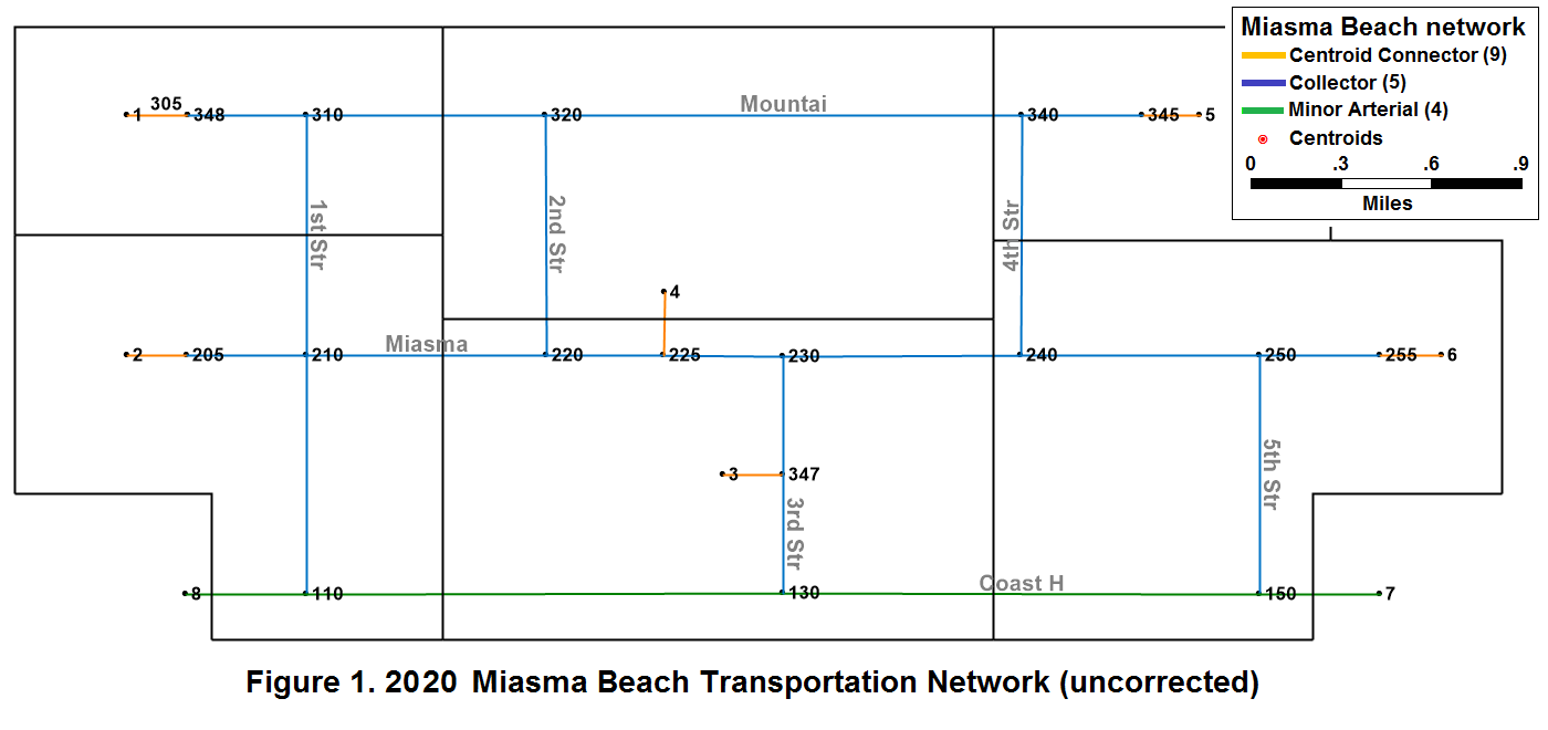
The first task is to create a TransCAD map file and to validate the zone system
and network structure. This 2020 data set does not correctly represent either
the 2000 or the 2020 Miasma Beach area (see Figure 1); it merely provides a starting
point to build the correct 2020 network representation, as detailed in the steps below.
               Table 1. Miasma Beach Speed-Capacity Table
     ------------------------------------------------------------------
          Link Type          Speed   Lanes  Capacity/Lane   Color
     ------------------------------------------------------------------
      1.  Freeway              60      2        1800        Purple
      2.  Primary Arterial     60      2        1200        Red
      3.  Major Arterial       45      2         900        Dark Green
      4.  Minor Arterial       45      1         600        Lght Green
      5.  Collector Street     30      1         600        Blue
      6.  Local Street         15      1         300        Cyan
      7.  Other Street          -      -           -        Yellow
      8.  Ramp                 30      1         600        Pink
      9.  Centroid Connector   25      9        1000        Orange
     ------------------------------------------------------------------
Task 1. VALIDATE 2020 BASE YEAR NETWORK
GIS/Modeling Concepts:
Why so many files with similar names?
To efficiently manage information pertaining to a layer, a GIS separates the
information into multiple files, all of which are required to generate the
Miasma Beach network in TransCAD. If you move to a new working folder,
copy all files to the new folder.
1.1 Create Base Miasma Map
Construct the TransCAD file that contains the GIS data for the draft 2020 Transportation System T and the Activity System A.
FILE ORGANIZATION: |
1.1.1 Open a Geographic File
Go to File / Open. In the File Open dialog box, select the folder
where you placed the Miasma Beach TransCAD data set (MB2020.zip, that contains
MB2020.* and Taz.*). Select Geographic File under the
List Files of Type. You should see MB2020.DBD and TAZ.DBD
in the file box. Select MB2020.DBD and click OK.
A "stick" network should be displayed. The network does not display end or intersection points. To see them, go to Map / Layers. In the Layers dialog box, under Layers in Order of Display, select Nodes (it is hidden now) and click the Show Layer button. Close this dialog box.
1.1.2 Add Another Layer
Go to Map / Layer again. Click the Add Layer button. In the
File Open box, open the Geographic File of TAZ.DBD. You should
now see the TAZ layer being added to your map. Some parts of the TAZ layer
may be displayed outside of the window. Go to Map / Scale and on the
Map Scale dialog box, select Show the Entire Layer of TAZ and
Selection Set All Features.
GIS/Modeling Concepts: Working Layer (or Current Layer) |
Examine the Map
Examine the map and compare it with Figure 1. Familiarize yourself with
this map and the characteristics of the various link, node, and zone attributes.
1.1.3 Save the Map
After you set up the display of the map to the way you want (which should be
labeled properly), go to File / Save As. In the Save As dialog box,
select the folder where you store your files. Select Map File under the
List Files of Type. Type in MB2020 under File Name
for your map and click OK.
GIS/Modeling Concepts: What is a *.map file? |
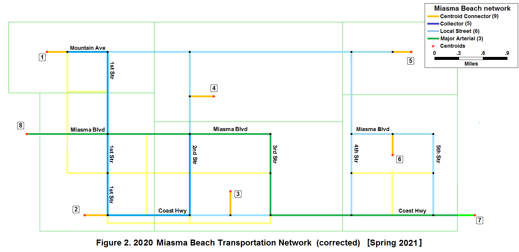
1.2 Network Updates
The input 2020 map has been incorrectly coded. Update the network to reflect the base 2000 network as well as network improvements planned in 2000 that have been implemented and must be reflected in the base 2020 network. Your network should match that depicted in Section 1.6. This may involve deleting links, adding or updating links, and/or moving centroids. Select Highways/Streets as the Working Layer to implement all network corrections identified below. Use Tools / Map Editing to adjust link attributes.
For a video example of how to edit a line network, click HERE
- Mountain is a local street east of 1st Street and a collector street west of 1st Street
- All of 1st Street is a collector street
- 2nd Street between Mountain Ave and Miasma Blvd is a local street
- 2nd Street between Miasma Blvd and Coast Highway is a collector street
- Add section of 4th Street from Miasma Blvd to Coast Highway as a local street
- All of 4th Street and all of 5th Street are local streets, as is Miasma Blvd between 4th and 5th
- Move centroid connector for TAZ 4 to connect on 2nd Street 0.5 miles North of Miasma Blvd
- Move Centroid 6 and tie its connector to the midpoint of Miasma Blvd between 4th and 5th streets
- Move Centroid 3 and tie its connector to the midpoint of Coast Highway between 2nd and 3rd streets
- TAZ 2 and ES 8 must be switched (add a link from the TAZ or ES to the correct node before deleting the existing link; then, update the link and move the node
- The link west of 1st Street at Coast Highway is a 0.25 mile centroid connector
- The link west of 1st Street at Miasma Blvd is a 1-mile major arterial
- Delete Miasma Blvd from 3rd Street to 4th Street (the Miasma Marsh wetlands)
- Update 3rd Street from Miasma Blvd to Coast Highway to a major arterial
- Update Miasma Blvd between 3rd and ES 8 to a major arterial
- Coast Highway from 1st Street to 2nd street is a collector street, and a local street from 2nd to 3rd
- Update Coast Highway east of 3rd Street to a major arterial
- Link types need to be updated based on state and county functional classification (see Table 1):
Change all links with LINK_TYPE "Primary" to "Major";
Change all links with LINK_TYPE "Second" to "Collector" (and GROUP_CODE to "Collector")
Verify that your network, including all link characteristics, matches that shown in Figure 2.
1.2.1 Delete Links
To delete a link, go to Tools / Map Editing (set the Working Layer
to Highways/Streets). The Map Editing tool box appears. Select the
Delete button and click on the link to be deleted (e.g., (1) above).
The color of the link changes and the Red Light and Green Light
buttons appear in the Map Editing tool box. Be sure you've selected the correct
link, and select the Green Light and the change will
be saved with the link being removed from the map (if you've selected the wrong
link, click the Red Light and the change will not be
saved). Note: Be careful to select only the link section desired -- you may need
to split a link first.
1.2.2 Add Links
To add a section of 4th Street between Coast Highway and Miasma Blvd, first
"split" the current link to add a node where the new link will connect.
|
HELP: Settings for Splitting Links: If assistance is needed in splitting links, then Click HERE VIDEO: For a video on editing, click HERE (at the 1:00 min timestamp). |
Joining Links: Select the Join Line button and click on both links to join them into a single link. As long as there are no node penalties or turn prohibitions, you can leave old nodes (they may be of use in the future).
Click on the Split Line button. Click on the midpoint of Mountain Blvd. between 2nd and 4th Streets. This should split this segment to two 1 mile stretches. Click on the info tool and then click on Mountain Boulevard between 3rd and 4th to adjust H_DIST as necessary. Repeat for other required split links. Select Add Line in the Map Editing toolbox and add links (single click on the start node, drag the mouse (a dash line appears) to the desired end node and double click). Click on the new line and fill in link attributes as appropriate. Follow the same procedure to add other sections, as required.
1.2.3 Move Centroid
To change the centroid location, split the section of Coast Highway between
the added section of 2nd Street and 3rd Street at the midpoint (0.5 miles west
of 3rd Street). Then add a line from the new split point to Centroid 3. Use the
Pointer Tool (arrowhead) to drag the centroid to a point 0.25 miles north
of the new split point. Use the Info Tool to edit this new line to match
the attributes of other centroid connectors. Finally, delete the old connector.
1.2.4 Edit Link Attributes
To change attributes of network links, use the Info Tool. To change
node numbers, you must select the node layer and open a node data view.
1.3 TAZ Updates
The TAZ.* files contain information regarding the traffic analysis zones in Miasma Beach, including demographic data. The zonal information stored in this TransCAD network is incomplete, you must fill in a few entries. Set TAZ as your working layer, and open the dataview.
VIDEO: For a video on how to edit an area network, click HERE.
Make the following updates/corrections:
- For Zone 2, change the Population (POP) value from 0 to 1550
- For Zone 5, change the Other Employment (EOTH) value from 0 to 50
- For Zone 5, change the Total Employment (ETOT) value from 0 to 150
- For Zone 6, change the Household Income (HHInc) value from 3800 to 38,000
- For Zones 1-6, increase Household Income by 50 percent to reflect income growth from 2000 to 2020
- For External Stations 7 and 8, set area (AREA) to 0 (they're doors, not TAZs)
GIS Concepts: Editing in a GIS GIS Concepts: Spatial Query |
1.4 Formulate Attributes
After network editing is complete, calculate the free flow travel time for both directions of each link. It is easier to do this task in a Dataview (a spreadsheet-like table that displays data for the entire layer) than using the Info tool because all links must be updated, not just a few.
|
HELP: Formulating Link Travel Times: If assistance is needed in Formulating Link Travel Times, then Click HERE VIDEO: For a video explanation, click HERE. |
GIS Concepts: Link Direction The direction a GIS draws a link is the topological direction of a link. This information exists internally in the database (e.g., in the MB2020 files). If you want to see a link's topological direction in Dataview, set Highways/Streets as the working layer and go to Dataview / Formula Fields. In the Formula (Dataview: Highways / Streets) dialog box, click on the Node Fields button. Another dialog box Node Formula Fields appears. Highlight ID and click OK. Two fields, [From ID] and [To ID], are added to the dataview. [From ID] is the ID of the link beginning node; [To ID] is the ID of the ending node. |
1.5 Enhance Miasma Map
Select Color Themes. With the Highway/Streets layer active, select the Color Theme Map Wizard. Select Link_Type under Field and List of Values under Method, then select the Styles tab to select colors. Use the link color theme from Table 1. You may also select line styles that will also distinguish link types. Label at least one link on each street with its name (Hint: Use Layers dialog Box).
VIDEO:
For a video tutorial on how to make make a color themed map, click
HERE.
1.6 Print Miasma Map
After you have verified that your network is correct, print the final map layers and generate reports documenting all data for inclusion in the interim report. Note that link ID alone is not suitable means to identify links in a table. Please include A-Node, B-Node, and/or link name.
1.7 Prepare Task 1 Documentation
Please label the first section Introduction and provide a brief summary of the prior Miasma Beach transportation study, including what planned improvements were actually implemented in the intervening 10 years. Label subsequent sections Chapter 1 through Chapter 6, corresponding to defined project work tasks. The last section should be labeled Summary and Recommendations.
Prepare Task 1 documentation, including TransCAD maps and tables. Append a project Glossary containing at least four key terms from the Task 1 analysis (the Glossary will be extended in each subsequent task). Use graphic capture and rendering tools. Follow Format Guidelines in the preparation of this document. This material will be submitted as part of the first Interim Report (see Task 2).
Video Summary: